Under construction
1967 - 1969 Mustang (including GT, Shelby GT-350, GT-500, GT500KR and Boss 429/302) dual-exhaust systems are supported in three places.
1 - Where the H-pipe attaches to the engine exhaust manifolds
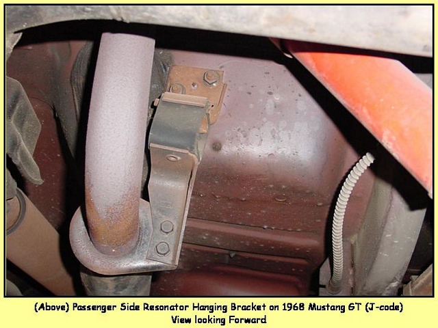
2 - Where the resonator hanging bracket attaches in the rear floor area
3 - Where the tailpipes attach to the rear frame
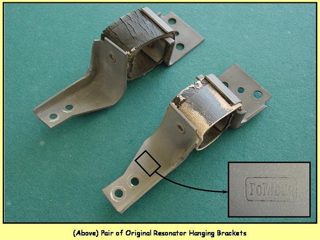
Resonator Hanging Bracket - All dual-exhaust Mustangs from 1967 - 1969 use the same resonator hanging bracket. Two brackets are required per car; one for the passenger side and one for the driver side. The two brackets are not identical, they are mirror images of each other, there is a left and a right bracket. The lower portion of the bracket attaches to the resonator bracket (welded to the resonator or pipe depending on application) with two bolts. The top portion of the bracket attaches to the floor of the car. And the top and bottom portions are secured together with a piece of rubber (tire sidewall) and two flat-head, semi-tubular rivets with backing plates. The metal parts are natural and not plated. The bottom metal portion of the bracket is nearly always stamped FoMoCo in a rectangle...although some originals escaped the stamping process. See Pictures below.
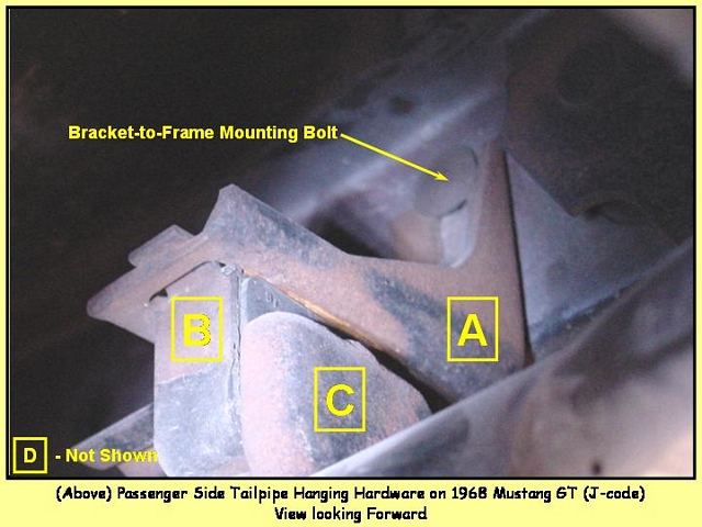
Tailpipe Hanging Hardware - Tailpipes for dual exhaust Mustangs from 1967 - 1969 use the same basic hanging hardware. This consists of 4-basic pieces:
- A) a bracket that attaches to the car frame at the rear of the car
- B) a rubber insulator that bolts to bracket "A"
- C) a stamped steel J-hook that goes through "B" and is clamped (D) to the tailpipe
- D) a tailpipe band clamp which goes around the tailpipe and the J-hook (C)
Below are two pictures of the basic arrangement of items A, B, C, and D. The tailpipe band clamp (D) is not visible in the first picture.
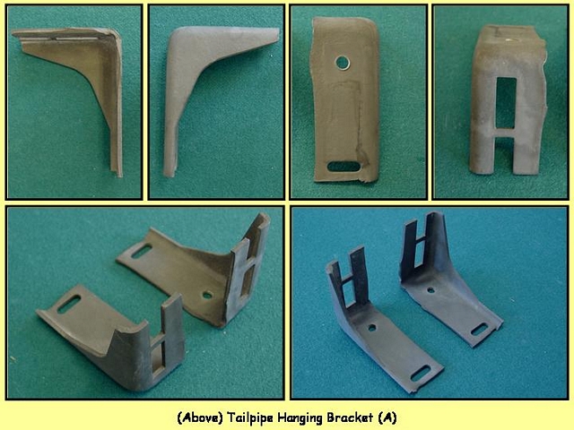
Tailpipe Frame Hanging Bracket (A) - The tail pipe hanging bracket bolts to the rear frame rail with two bolts which go completely through the frame rail and are secured by two nuts. The bracket is adjusted up-or-down by two rectangular slots (one open). Two brackets are required per car; one for the passenger side and one for the driver side. The two brackets are not identical, they are mirror images of each other, there is a left and a right bracket. The bracket has a natural/bare steel finish and is not plated. The brackets are not marked by Ford, there is no FoMoCo stamp, or "L" or "R" indications. Pictures of the brackets are shown below.
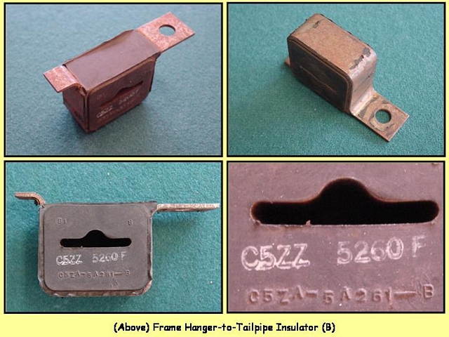
Frame Hanger to Tailpipe Rubber Insulator (B) - The rubber insulator assembly is made of two pieces. A metal frame that allows the insulator to be hooked into bracket (A) on one end, and bolted to bracket (A) on the other end. Molded to the metal frame is a black rubber insulator. In the middle of the rubber is a contoured hole for the J-hook (C). The rubber has a part number (C5ZA-5A261-B) molded into it at the bottom. Service parts also have the part number stamped on the rubber in white ink. The white stamp was probably not on the assembly line parts, only the service parts. The same part is used for the left and right tailpipes. Pictures of the insulator are shown below.
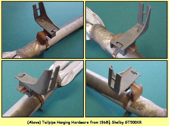
J-Hook (C) - The J-hook is a stamped metal part that is inserted into the insulator and clamped to the tailpipe. The same part is used for both left and right. The metal is natural/bare steel and not plated. The flat metal portion of the bracket is nearly always stamped FoMoCo in an oval with a "G"...although some originals escaped the stamping process. Pictures of the J-hook are shown below. |
